![]()
One way of trying to answer these questions is to understand the subtle differences in the behavior between matter and artificially produced anti-matter. This is done by colliding electrons with anti-electrons, "positrons." You can, incidentally, make positrons by colliding energetic electrons into a block of metal. If the electrons and positrons collide, and if they are sufficiently energetic, the annihilation products of the collision include quarks and anti-quarks. We are mostly interested in studying the behavior difference between "beauty" and anti-"beauty" quarks, our samples of matter and anti-matter.
The instrument that collides electrons and positrons and that produces our samples of beauty and anti-beauty quarks is the Cornell Electron Storage Ring (CESR). This is a circular device 770 meters in circumference located at Cornell University and funded by the National Science Foundation. The multi-purpose instrument that detects the collision beauty and anti-beauty quarks is the CLEO detector. It is staffed by faculty, post-docs and graduate students from 23 or so North American universities, of which SMU is one.
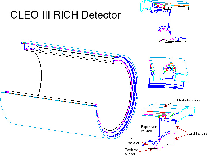
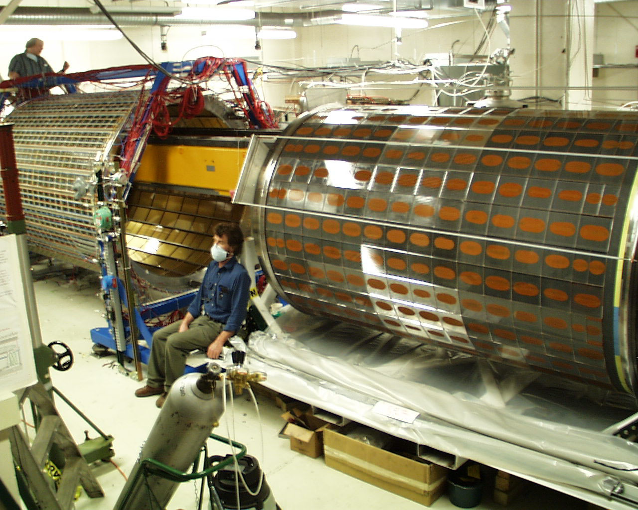
The SMU High Energy Physics group built the solid LiF radiator for the Ring Imaging Cherenkov Counter (RICH) for the CLEO III upgrade. This device is now joined with an ensemble of photon detecting modules produced at a collaborating university to produce a RICH, a kind of speedometer for sub-atomic charged particles moving with speeds close to that of light. Information from the RICH is combined with information from other CLEO sub-detectors to determine the mass of the charged particle. Since charged particles have unique masses, measuring a particle's mass identifies it. RICH is built to identify charged particles. The entire CLEO III detector is shown here.

For the RICH to work, it is necessary that the emitted Cherenkov light escape from the material where it is produced and eventually be detected. Although all materials can in principle emit Cherenkov light, only a small number are actually transparent to the light. The radiator material for the RICH is lithium fluoride (LiF), a non-organic salt transparent to much of its Cherenkov light. LiF also has a relatively low mass density, a required feature for the proper functioning of the sub-detector that lies just outside the RICH. The Cherenkov light is eventually detected by a device known as a "multi-wire proportional chamber." This object is box filled with a special gas and containing wires held at high voltage. The Cherenkov light ionizes the gas and the liberated electrons drift toward the wires where they produce a microscopic spark. Electronics mounted on the chamber detects the spark positions so that you can image the original Cherenkov cone. The overall RICH scheme is shown in the figure below.
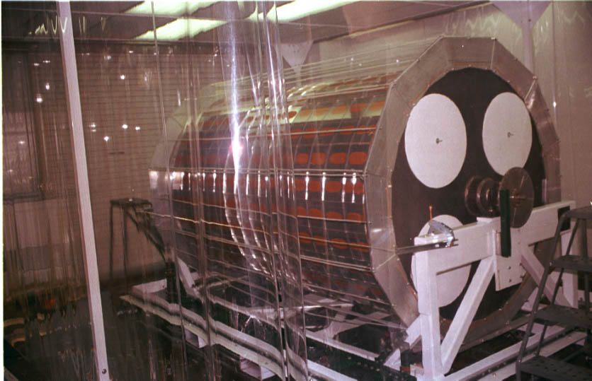
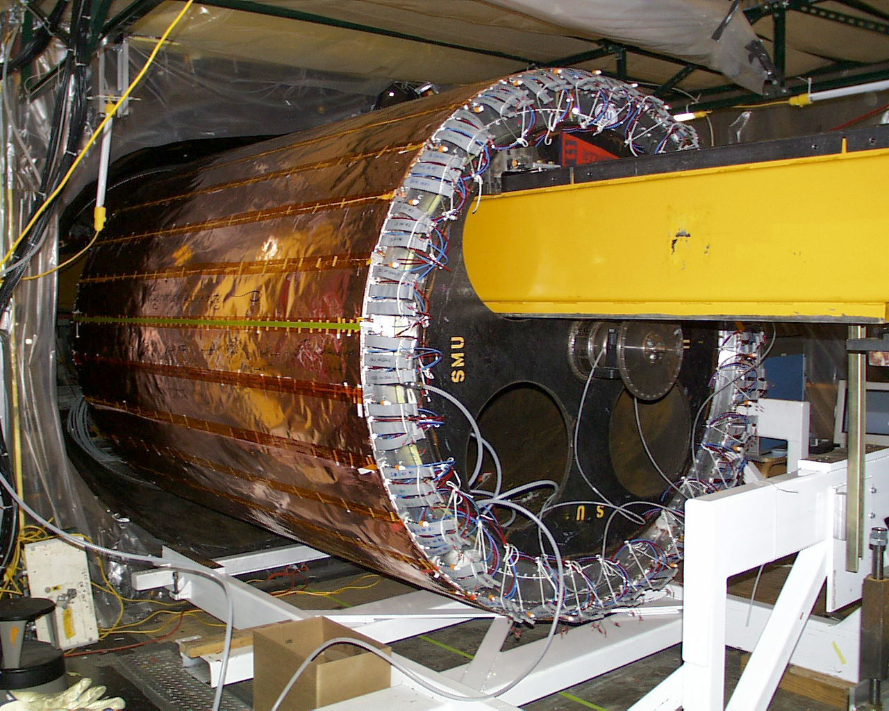
The RICH radiator is not actually a perfect cylinder because that is too hard to manufacture. Instead, the cylindrical geometry is approximated by building the radiator from 420 individual LiF rectangular tiles, each about 17 cm on a side and 1 cm thick. The tiles are arranged in 14 rings of 30 crystals each so that seen end on, the radiator is not a circle but a polygon of 30 sides. The tiles are aligned and attached in a manner described below to a thin carbon fiber cylindrical shell which forms the ultimate mechanical structure of the radiator. This 1.5 mm thick shell is in turn temporarily wrapped around a steel mandril to maintain its cylindrical shape during radiator construction. The mandril is discarded after the entire RICH is installed inside CLEO. The figure below shows the carbon fiber cylinder wrapped around its mandril.
A schematic view of the radiator is shown here. Notice the two crystal types. The central crystals have a "sawtooth" pattern cut into them to allow the light emitted inside the crystal to escape. Without this shape, all the light would be trapped inside these crystals due to the phenomenon of "total internal reflection," the same phenomenon, for example, which makes a telephone optical fiber work. Far from the radiator center, this special shape is unneeded and the crystals have a simple planar shape for manufacturing ease. The completed radiator is 1.6 meters in diameter and approximately 2.5 meters long.
After a crystal is measured and certified to be sufficiently clear and to have the proper shape, it is carefully stored in an aluminized plastic bag containing dessicant. The crystals remain in this dry environment until they are ready for mounting.
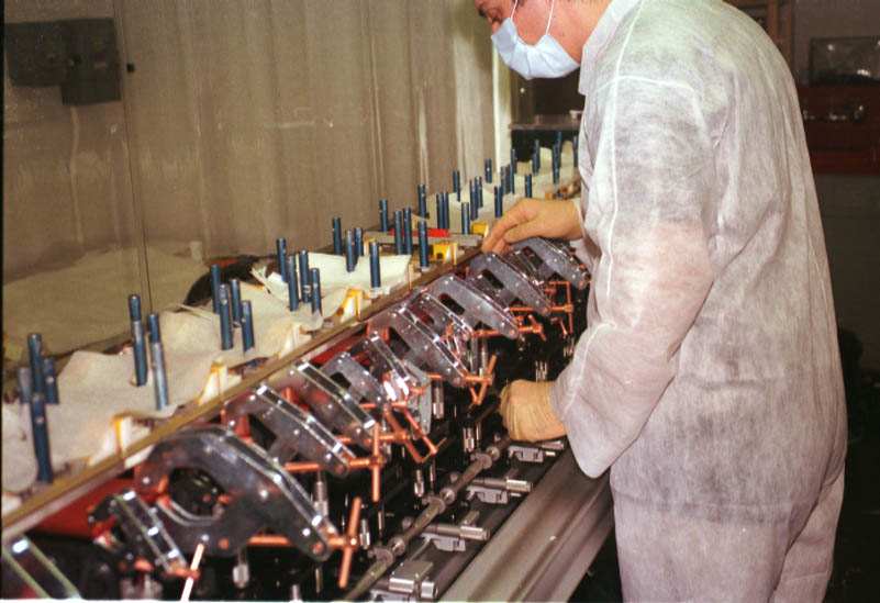
While resting on the mandril stages and still attached to the transfer tool, a crystal row is aligned with respect to the axis of the support shell to ensure that the row is not wrapped like a helix around the shell. Epoxy is then applied to the support shell beneath the center of each crystal and the transfer tool is lowered by its stages to set the gap between the bottom of the crystal row and the support shell. After the epoxy cures, the picture frame jigs are disconnected from the attached crystals, the transfer tool is removed from the mandril, and another crystal row is built. The mandril is then rotated to accept the next crystal row and the entire alignment and attachment process repeats until all 30 crystal rows are attached to the support shell. The picture below shows the transfer tool and its crystal row just prior to attachment to the shell. Previously attached rows are visible. The rust colored regions are the epoxy locations.
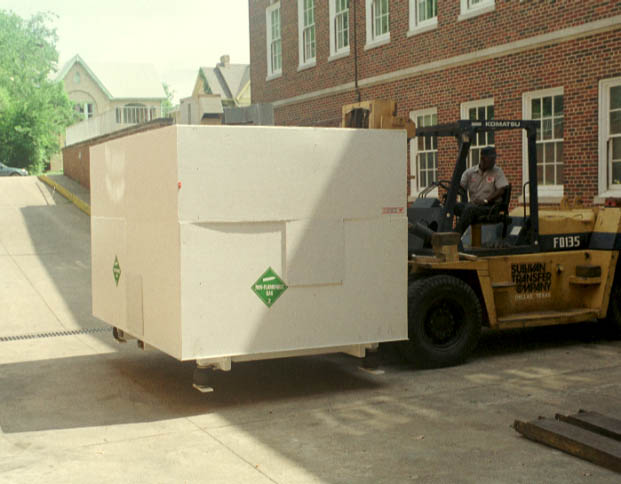
After sealing, the radiator is crated and prepared for shipment. Instrumentation for measuring accelerations and temperature is installed and air bags at the four corners of the mandril support frame are activated to dampen vibration during transport. The crated radiator is extracted from the cleanroom by a 15-ton forklift and then loaded onto a truck for local transportation through Dallas. (See the left hand side picture.) Afterwards, the crated radiator is loaded into a large van with a specialized air suspension system and temperature control for shipment from Dallas. (See the right hand side picture.)


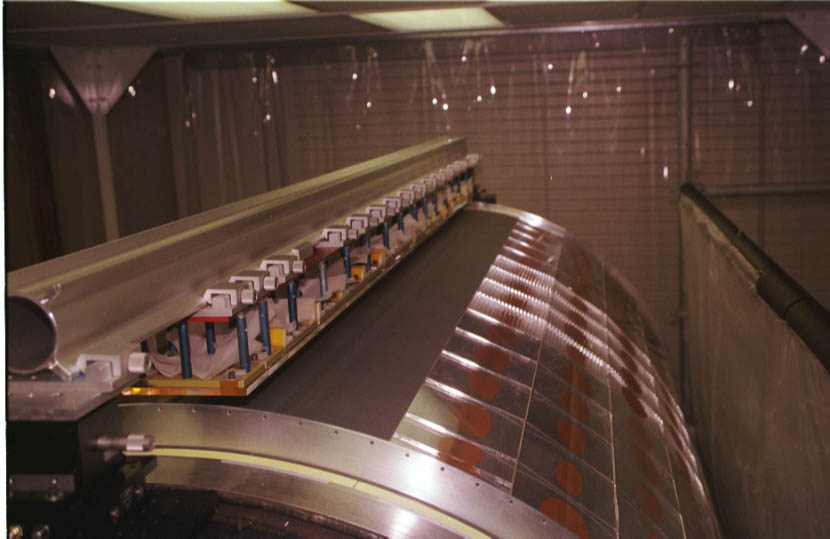
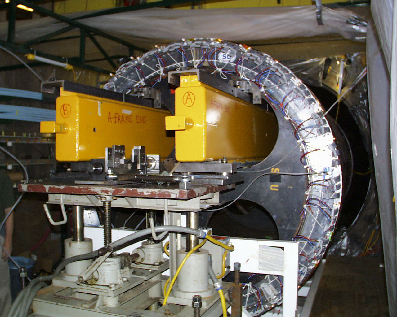
To perform the actual mating, the axes of the radiator and the light detection modules are first carefully aligned by using two long steel rails that thread both devices. Then, the radiator slides along the rails until it is fully inserted inside the modules. The two devices are then bolted together. The next picture shows the yellow transfer rails threaded through the detection modules and the mandril supporting the radiator.
This work was supported by the Department of Energy and the National Science Foundation.
T.E. Coan <coan@mail.physics.smu.edu>
