Lenses
SPECIFIC OBJECTIVES
To understand the difference between converging and diverging lenses;
to build a working telescope.
EQUIPMENT
Lenses, lens carriers, optical bench, light source, screen, paper grid pattern.
BACKGROUND
Lenses work by bending rays of light in a phenomenon called refraction,
the same process we studied in the prism
experiment. Refraction occurs whenever light passes from a medium
with one index of refraction to another medium with a different index of
refraction. When light enters a less optically dense medium (lower index
of refraction), it bends away from the perpendicular. When light enters a
more optically dense medium (higher index of refraction), it bends toward the perpendicular.
The surface of a lens is curved, but the law of refraction stated above
still holds at every point on the curved surface.

The figure below shows the path of some light rays from a point object
through the a positive lens. You see that the lens refracts the rays
passing through the edge of the lens while not refracting the ray that
passes through the center of the lens. All of the rays from a point
object converge at the same spot, producing a point image.
When the rays coming from the object are parallel, as occurs for very
distant objects (farther away than about 50 focal lengths), an image forms
at a distance from the lens called the focal length.
The focal length of a lens is determined by the index of refraction of
the glass used and by the curvature of its surface. Once the lens is
manufactured, its focal length is fixed.
In the figure of a positive eyepiece telescope below, F is the focal
length of the objective lens and f is the focal length of the eye lens.
The telescope has a theoretical magnifying power given by
M = - F / f
There are two kinds of images formed by lenses, real and virtual.
A real image can be projected onto a screen. A virtual image appears between
the lens and the object and cannot be projected on a screen.
Virtual images can be formed by both converging and diverging lenses. Real
images, however, can only be formed by converging lenses.
PROCEDURE
Positive and Negative Lenses
- Place each of the four lenses on a page of text. When lifted
slightly off the page, some lenses will magnify the text - these
are converging or positive lenses. Others will make the text look smaller
- these are diverging or negative lenses.
- Hold one of the positive lenses at arm's length and look through
it at some distant object. Does the image appear to hover between
your eye and the lens? Or does the image appear to hover between the
lens and the distant object? Is the image upright or inverted? What
kind of image is this (real or virtual)?
- Hold the negative lenses at arm's length and look through
it at some distant object. Does the image appear to hover between
your eye and the lens? Or does the image appear to hover between the
lens and the distant object? Is the image upright or inverted? What
kind of image is this (real or virtual)?
Determination of Focal Length
- Determine the focal length of each positive lens by placing it on the optical bench between the light source and the screen.
- Move the light source to one extreme on the optical bench. Move the
screen to the other extreme on the bench. The vertical lines on the carriers
give the position to the nearest half millimeter.
- Slide the lens carrier along the optical bench until a sharp image
of the source is formed on the screen.
- Measure the object distance do between the light source and
the lens, with an error estimate (the lens can be moved a certain distance
with no apparent effect on the sharpness of the image). Measure the
image distance di between the lens and the screen, with an error
estimate.
- Find the focal length of each positive lens using the lens grinder's
equation:
1 / f = 1 / do +
1 / di
- Is the image on the screen inverted or upright?
- Is the image on the screen real or virtual?
- Cover half of the lens with a piece of paper. What happens to the image?
- Verify that the negative lens will not form an
image on the screen. Therefore, this method cannot be used to determine
the focal length of a negative lens.
Making a Telescope
- Select the positive 200 mm focal length lens --
this will be the objective lens. Select the positive 100 mm focal length lens -- this will be the eye lens.
- Remove the light source and screen from the bench. Mount the
objective and eye lenses on the bench and adjust their separation to
the sum of their two focal lengths. Position the optical
bench so that it is aimed at something far away from you (Airline Garage).
- Place your eye up close to the eye lens. Look
toward the distant object through the eye lens and adjust the separation
until you see a clear image. You now have a simple telescope.
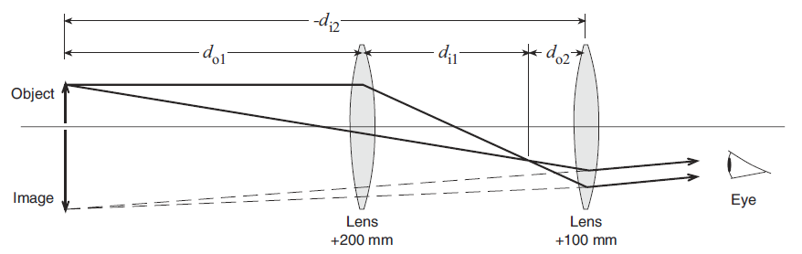
An astronomical telescope consists of two convex lenses. The astronomical telescope in this experiment will form an image in the same place as as the object (see figure above).
The lenses are thin compared to the other distances involved which allows the thin lens equation to be used:
1 / f = 1 / do +
1 / di
Magnification, M, is the ratio of the image size to the object size. If the image is inverted, M is negative. The magnification for a thin lens is:
M = (- di / do)
The magnification, M, of a two-lens system is equal the product of the magnifications of the individual lenses:
M = M1 M2 = (- di1 / do1) (- di2 / do2)
Object at Infinity
Look through the lenses at a distant object. Adjust the distance
between the lenses to focus the telescope with your eye relaxed. Estimate the
observed magnification. Now calculate the magnification by taking the ratio of the
focal lengths of the lenses. Compare the calculated magnification to the observed
magnification.
Galilean Telescope
Make a new telescope using the -150 mm lens as the eyepiece and the +250 mm lens
as the objective lens. Look through it at a distant object. Adjust the distance between
the lenses to focus the telescope with your eye relaxed. How is the distance between
the lenses related to their focal lengths?
How does the image viewed through this telescope differ from that of the previous
telescope? Is the magnification positive or negative?
Sketch a ray diagram for this negative eyepiece telescope similar to
the figure above for the positive eyepiece telescope. Make your sketch
large and clear, noting any significant differences from the diagram of the
positive eyepiece telescope.
What is the focal length of the negative lens? There are two ways to estimate this -- try them both and compare the results.
Analysis
- For each positive lens, find the error in the focal length using
( f) /
f2 =
(
do) / do2 +
(
di) / di2
f) /
f2 =
(
do) / do2 +
(
di) / di2
- For the positive eyepiece telescope, find the error in the
theoretical magnification. Does your experimental value fall within
this error range?
- Discuss random and systematic errors in this experiment.
 Back to the Electricity and Magnetism Manual