Electric Field and Electric Potential
SPECIFIC OBJECTIVES
To determine the shape of equipotential surfaces and electric field lines
associated with (a) two point charges (called a dipole when + and -) and
(b) two parallel plates, and to compare each of these to theoretical
predictions.
EQUIPMENT
Overbeck Electric Field Apparatus with a probe, a two-point board and a
parallel-plate board, multimeter
used as a galvanometer, 2 sheets of standard paper, power supply,
analog voltmeter, hook-up wire.
GLOSSARY
- COULOMB'S LAW is that the magnitude of the force (F) that
one point charge (q) exerts on another point charge (q') separated by a
distance (r) is given by
F = kqq' / r2
where k is a proportionality constant. The direction of
the force is along the line between the two charges. Like signed charges
repel and unlike signed charges attract.
- The ELECTRIC FIELD (E) at a point is defined to be the
Coulomb electric force (F) per unit positive charge (q) at the point
E = F / q
Note that E is a vector in the direction of the force F
on a positive test charge and has units of N/C (newtons per coulomb).
- The ELECTRIC LINE OF FORCE is the path a free positive test
charge would follow so its direction is generally away from positive
charges and towards negative charges. The electric field is tangent
to the electric line of force. The strength or intensity of the
electric field can be described graphically through the density of
electric lines of force: the electric field is strongest where the lines
appear closest together.
- The ELECTRICAL POTENTIAL difference or VOLTAGE difference
(V) between two points is defined to be the work (W) done by the electric
force in transporting a unit of positive charge (q) from one point to another.
V = W / q
Note that electric potential (or voltage) is a scalar quantity and the
unit, volt, is defined to be V = J/C (joule per coulomb). Note also that
if work is done on the positive test charge being transported, then its
potential energy increases and it goes to higher (more positive) electric
potential energies.
- An EQUIPOTENTIAL SURFACE is a mathematical surface on which a
test charge can be moved without any electrical work being done. Since
work involves parallel components of force and displacement, it follows
that equipotential surfaces and electric lines of force are everywhere at
right angles, i.e., the test charge must move perpendicular to E-lines
(direction of force) if no work is done.
- The ELECTRIC CURRENT (i) is the rate at which charge flows.
The unit, ampere, is defined by A = C/s (coulomb per second).
The direction of current flow is the direction in which positive charge
moves, which is opposite to the direction in which negative charge moves.
Since negatively charged electrons carry the current in most materials,
it is important to remember that current flows opposite to the way the
electrons are moving.
- The ELECTRICAL RESISTANCE (R) of a device is defined to be the
ratio of the voltage (V) across the device to the current (i) through the
device R = V / i. The unit of resistance, ohm
(
 , the Greek
letter capital omega), is then defined to be the resistance when one volt
exists across and one amp flows through the device,
 = V/A.
- A GALVANOMETER is a very sensitive current detector which can
read current passing through it in either direction i.e., a sensitive,
unpolarized ammeter. Its usual function is to indicate a zero current
circumstance.
BACKGROUND
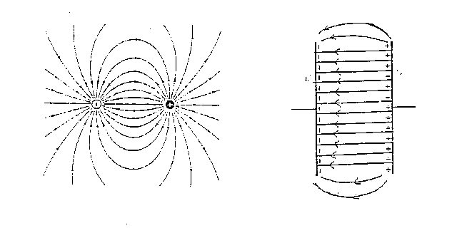
From the definitions, electric field shapes are envisioned as families of
electric lines of force. Since a line is the path followed by a free
positive test charge, the shape and direction of a field about an isolated
simple charge distri bution is predictable using Coulomb's Law. Consider an
electric dipole which consists of a positive and a negative point charge
separated by some distance. Imagine that a small, positive lest charge is
released near the +q and consider the path it would follow under the two
forces acting on it. The test charge is repelled by the +q and atracted to
the -q, weakly or strongly depending on the separation distances according
to Coulomb's Law. At every point along the line the net force must be
tangent to the line in order to move it along that path. In general, the
field of a dipole originates from the +q, bows outward and terminates on
the -q. Most general physics textbooks provide an accurate representation
of the field of a dipole and other point charge configurations.
Predicting the electric fields of continuous charge distributions such as
charged wires or plates is more difficult than for point charges. The
methods of calculus are generally used for continuous charge distributions
and general physics texts usually provide predictions for the more common
distributions such as charged parallel plates. Consider two oppositely
charged parallel plates whose dimensions (area) are large compared to the
separation between the plates. The predicted field bows outward at the
ends (called edge effects); however the more important predictions are
that, within the central region between the plates, the electric field has
a constant magnitude and is directed perpendicular to the plates from the
positive to the negative plate. Theoretically predicted diagrams are shown
below.

While theoretical predictions of electric fields for simple charge
distributions are readily available, their experimental determination can
be tedious. One method is to determine the equipotential lines (or
surfaces) and then construct the electric lines everywhere at right angles
to the equipotentials. If two points are on an equipotential surface, then
the electric current between the two points must be zero. (V = Ri, V = 0
and R is not 0, so i = 0) A sensitive, null detecting ammeter, called a
galvanometer, may be used to locate points on equipotentials.
PROCEDURE
- Using the two screws provided, install the two-point charge plate on
the underside of the board so that the black side is down or away from the
board.
- Use masking tape to secure an 8.5" x 11" page of paper to the top of
the board. The four legs are spring loaded and the corners of the page can
fit under them. Use any method to locate the two point charges and mark
them on your paper.
- Turn the power supply off and the voltage control fully counter-clockwise
to zero before connecting it to 110V. AC. Connect the 0-10 DCV meter
across the power supply with correct polarities. (+ to + or red-to-red) to
use as a voltage monitor.
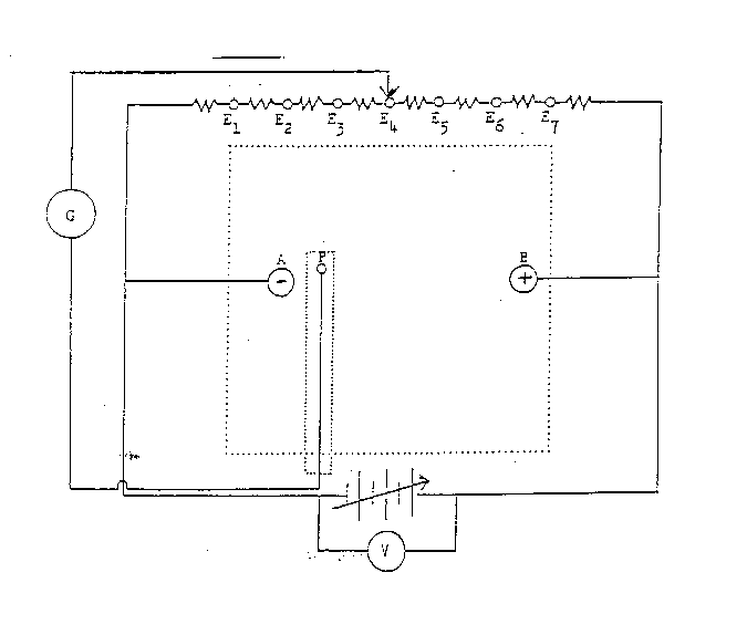
- Connect the power supply across terminals A and B observing that A is
negative and B is positive as shown in the diagram below.

- Read the precautions for using a
multimeter as a current meter.
- Set the multimeter, which is to function as the galvanometer (G), on
the smallest current range and DCA (direct current amps) function. Connect
G between terminal E4 and the probe.
- Separate the probe enough to fit it over the board with the metal contact
touching the black surface and the small hole on the probe above the
paper. The board is now ready for use and should be connected as
represented in the diagram above.
- Turn the power supply on and adjust it to about 8.0 V. (The exact voltage
used is not critical because this would not affect the shape of the field
even though it does affect the strength of the field.)
- With moderate pressure between the probe contact and the black surface
of the plate, move the probe to various points between A and B until a
point is found where G reads zero and mark this point through the hole in
the top of the probe . Finding this null point may be tedious because G is
very sensitive and slight variations such as probe pressure may cause it to
fluctuate. If it fluctuates between + and - (zero is surely somewhere in
between!), this probably is an adequate "zero" reading. Practice finding
the null points until a satisfactory technique has been achieved. Realize
that each null point found is at the same potential (voltage) as is E4
because no current flows from E4 to the point (P). Thus, all null points
found while G is connected to E4 are at the same potential and, therefore,
form an equipotential line.
- With G connected to E4, find a series of null points and mark each with a
pencil through the hole in the top of the probe. There should be enough
(8-10) points to allow sketching a smooth curve between them and they
should extend from near the top to near the bottom of the page. They need
not extend to the left or right beyond the area between A and B. Sketch
the smooth curve connecting the null points freehand; do not use a ruler.
- Repeat the previous step using other E-points instead of E4 to locate
points on other equipotentials. Continue this repetition until
equipotential lines for E3, E2, E1, and E5, E6, E7 have been found. (Don't
expect perfection in these equipolential curves because the field is likely
to be somewhat distorted by the metal parts of the plate and the metal
under the table. A conducting material such as most metals, must be
considered an equipotential surface so, if E-lines terminate on the surface
of a conductor, they must do so at right angles to the surface. Thus, any
metal in the immediate vicinity of an E-field could distort the field
noticeably.)
- Replace the page of paper with a clean sheet and mark the location of
the parallel plates on it. Replace the two-point charges plate with the
plate having the parallel plate configuration on it. Repeat the two
previous steps for the parallel plates.
ANALYSIS
The two pages, one for point charges and one for parallel plates,
constitute the raw data. Each partner should analyze both pages and keep
one in each lab notebook. By freehand, draw smooth curves through
each of the equipotential sets of points found. Sketch in the electric
lines so that they are everywhere at right angles to the equipotential
lines. Label the polarity of the charges and plates and assign directions
(arrows) to all E lines for both pages. The two electric field
configurations thus obtained should provide the basis for conclusions to be
reached. Partners should each make notes in their individual notebooks that
could be used in writing a formal report.
Each partner must answer the following questions in his or her own notebook.
- In what general region or regions is the point-charge field strongest?
How do you explain this observation? How, if at all, is this related to
line density?
- In terms of the equipment used, what is the principal explanation or
reason for anomalies (deviations from theory) found in the two fields?
- Identify at least two sources of random (statistical) error.
- Identify at least two sources of systematic error.
CONCLUSION
Summarize what you learned today (not what you did).
 Back to the Electricity and Magnetism Manual


 Back to the Electricity and Magnetism Manual