Kirchhoff's Laws


ALL THE TABLES ON ONE PAGE FOR EASY PRINTING

SPECIFIC OBJECTIVES

EQUIPMENT

Circuit board, D-cell batteries (2), wires, resistors, multimeter, and probe leads.

SYMBOLS FOR CIRCUIT ELEMENTS

In this lab you will be using many electrical components, all of which will be symbolized in schematic diagrams. You will need to recognize these components in order to perform the lab effectively.

Circuit elements

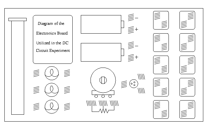
CIRCUIT BOARD DIAGRAM

Circuit board

PROCEDURE

The underlined passages below require an answer or a sketch in your notebook.

Part 1 - Current in Series and Parallel Circuits

  1. When you are not taking data, please disconnect the battery; this will increase its lifespan.

  2. Choose three resistors with identical coded resistance. The bands should be the same; the color and shape of the resistor body may vary.

  3. Record the coded resistance and the tolerance in table below. Record the series equivalent resistance in the 4th row of the table. Either use circuit theory to calculate the series equivalent resistance or simply use the ohmmeter to measure the resistance across all three resistors (make sure the battery is NOT connected when measuring resistance!).

  4. Connect the three resistors in the series circuit shown below, using the springs on the lower part of the board to hold the resistors.

    Three resistors in series with a battery


  5. Review the precautions for using a multimeter as a voltmeter.

  6. Measure the voltage across each of the resistors in turn and record your measurements (with units and errors) in the table below. Record the voltage across the battery in the 4th row of the table.

    To discover the correct setting for the meter, start the meter off at the largest setting, then work down to smaller settings, and stop at the setting which can handle both the size of the data to be measured and has the most number of significant digits in the reading.
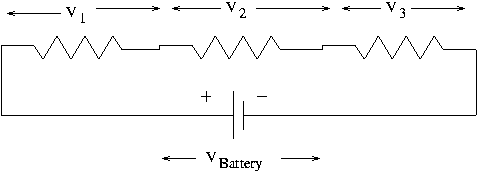


    Three resistors in series with a battery


  7. Review the precautions for using a multimeter as an ammeter.

  8. Review them again. Be ABSOLUTELY sure you know how to measure current correctly. Both you AND your lab partner will lose two points if either of you blows the fuse in the multimeter.

  9. Break the circuit open at the point indicated in the figure below. Measure the current I1 flowing through the wire between the positive terminal of the battery and resistor 1. Record your measurements (with units and errors) in the table below.

    Three resistors in series with a battery


  10. Remove the ammeter, reconnect the circuit, and break the circuit open between resistor 1 and resistor 2. Measure the current I2 flowing through that piece of wire. Record your measurements (with units and errors) in the table below.

  11. Repeat for current I3 flowing between resistor 2 and resistor 3, and current I4 flowing between resistor 3 and the battery.

      Resistance Voltage Current
    1   
    2   
    3   
    4   


  12. What is the apparent rule for current in a series circuit?

  13. Repeat this exercise with three non-identical resistors.

      Resistance Voltage Current
    1   
    2   
    3   
    4   


  14. Does the apparent rule still hold? Explain.

  15. Does Ohm's Law V=IR hold true for each individual resistor? Explain.

  16. Does Ohm's Law hold true for the series equivalent resistance (fourth row of the table)? Explain.


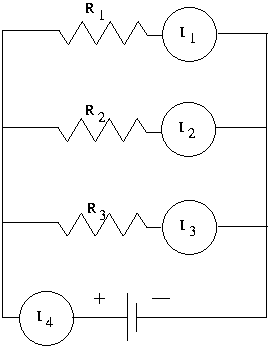
  17. Build a circuit with three identical resistors in parallel.

    Three resistors in parallel with a battery


  18. Record the coded resistances and tolerances in the table below. In the fourth row, record the theoretical parallel equivalent resistance. Or you can measure the equivalent resistance with the ohmeter function of the multimeter, but be sure to disconnect the battery!

  19. Record the voltages across each resistor (1,2,3) and the battery (4).

  20. Measure the currents through each resistor (1,2,3) and the current flowing out of the battery (4). Remember to break the circuit open and insert the ammeter in series.

      Resistance Voltage Current
    1   
    2   
    3   
    4   


  21. What is the apparent rule for current in a parallel circuit?

  22. Repeat this exercise with three non-identical resistors.

      Resistance Voltage Current
    1   
    2   
    3   
    4   


  23. Does the apparent rule still hold? Explain.

  24. Does Ohm's Law V=IR hold true for each individual resistor? Explain.

  25. Does Ohm's Law hold true for the parallel equivalent resistance (fourth row of the table)? Explain.


Part 2 - Kirchhoff's Laws

  1. When you are not taking data, please disconnect the battery; this will increase its lifespan.

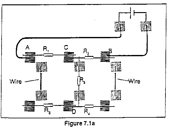
  2. Connect the circuit shown below, using

    Picture of circuit for Kirchhoff's Laws


    Circuit diagram  for Kirchhoff's Laws


  3. Record these resistance values with tolerances in the table below.

  4. Are any resistors in series or parallel? Can any resistors be combined into series or parallel equivalent resistances?

  5. With no current flowing (battery disconnected) measure the resistance between points A and B, and record this value in the last row (B for battery ) of the table.

  6. With the battery connected, measure the voltage across each resistor. Record the values in the table. Also measure the voltage from point A to point B and record in the last row of the table. On a diagram like the one above, mark the polarity of the voltage. That is, mark a "+" or "-" on the sides of the resistors to indicate which side is at the higher voltage and which is at the lower voltage. The multimeter will display a positive reading if the red probe is at a higher potential than the black probe.

  7. Measure the current flowing through each resistor and record these values in the table. Also measure the current flowing out of the battery and record it in the last row of the table. Remember to break the circuit open and insert the ammeter in series.

      Resistance Voltage Current
    1   
    2   
    3   
    4   
    5   
    B   


  8. Determine the net current flow into each junction. If current is flowing out of the junction then it is negative.

  9. Determine the net voltage drop around two of the seven closed loops in the circuit. Diagram which loops you are using.

  10. Do Kirchhoff's two rules hold experimentally for this circuit? Explain.

  11. Does Ohm's Law V=IR hold true for each individual resistor? Explain.

  12. Does Ohm's Law hold for the entire circuit? That is, does it hold for the last row of the table? Explain.


Don't forget your two random and two systematic error sources.


<-- Back to the Electricity and Magnetism Manual