 LAr Calorimeter Notes
 LAr Calorimeter Notes
  |

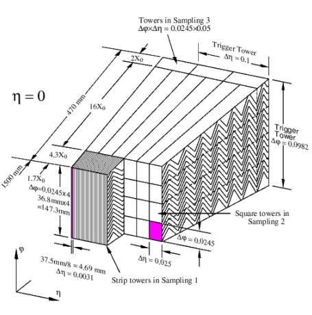
3 Sampling regions (determined by cell granularity).
η-ϕ segmentation into towers. The cross-section (in η-ϕ) of a Sampling 2 tower is 4x4 cells.

Note: info given here is based on Columbia U. FEB note [pdf].
Readout.
Preamplifier: amplification. Depending on its amplitude, the signal amplified with 3 fixed gains (High=100, Medium=10, Low=1).
Bipolar Shaper: Shaping.
SCA (analog): Sampling at 40 MHz and storage.
Gain Selector: Digitization
by 12-bit ADC. ADC
digitization happens after the SCA controller receives Level 1 (L1)
trigger accept.
| During calibration DAC, delay and pattern are loaded via SPAC protocol onto the TTCRx chip. Pattern in this case is the set of calibration lines to be turned on. Each pattern is a set of 128 bits (four 32 bit words). See also item 10 |
TTCRx: The 40 MHz TTCRx output clocks are fanned out to operate various FEB components. In addition, it transmits the L1 accept, Bunch Counter Reset (BCR), and Event Counter Reset (ECR) signals to the SCA Controllers.
SPAC Slave: part of TTCRx which allows it to be externally configured and reset.
|
During calibration DAC, delay and pattern are loaded via SPAC protocol onto the TTCRx chip. ¶ Pattern is the set of calibration lines to be turned on. Each pattern is a set of 128 bits (four 32 bit words). See also item 10. ¶ DAC is chosen between 0 and 65535. ¶ Delay value range for 2004 Test Beam was 0-24 counts with 1.04 ns steps, which allowed to scan the shaped pulse every 1.04 ns. |
Read-Out Driver (ROD): Transmission of digitized signals to off-detector via 1.6 GHz optical link.
Dynamic range of the accepted signal: 16 bits.
Design goal: Contribution to the constant term in calo resolution: < 0.25%.
Store sampled signals in Switched Capacitor Array (SCA) during level 1 trigger (L1) latency of up to 2.5 μs.